What is Phased Array Ultrasonic Testing
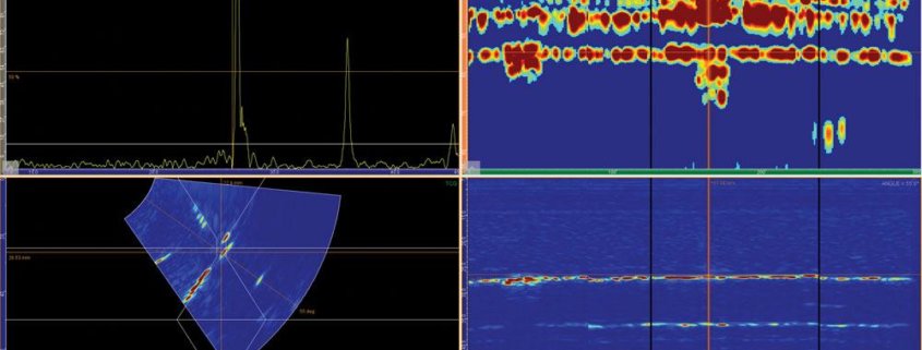
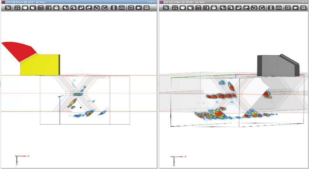
With PAUT, the technician actually gets images of the scanned areas in A, B, C, and D forms, which then can be generated into 3D images using the appropriate software.
What if ultrasonic results were presented in picture form instead of a written report? What if 3D images of welds were available for a welder to review at any time? What if all this data could be kept in digital form? And what if your confidence for the probability of detection (POD) soared from 50 percent to over 90 percent?
These are the questions that Andrew Crawford, TQMS manager for Buffalo Inspection Services in Edmonton, posed at his presentation during this year’s CanWeld event as he introduced the audience to the latest in phased array technology.
Non-destructive testing (NDT) has been an essential component for the production of quality parts in the fabricating and welding sector for decades. For general methods of testing, including eddy current (ET), magnetic particle (MT), liquid penetrant (PT), radiographic (RT), ultrasonic (UT), and visual testing (VT), the physics behind them hasn’t changed significantly since their inception into the market. However, NDT has become more advanced through innovation and technology trends. The hardware for these methods will become more affordable, but it is the software that will determine functionality.
New ways to collect and interpret data will in time push methods to their limits, eventually phasing them out to make way for advanced methods. Crawford used the example of how shear wave single crystal technology, which has been around since the 1950s and still being certified in Canada, is slowly being phased out by more advanced technology like phased array ultrasonic testing (PAUT).
PAUT
PAUT is a newer method of NDT that became commercially available in the 1990s in a portable form, after the release of Windows 3.1, and evolved from the traditional UT method of single-crystal technology combined with software and computing power to allow multiple crystals to work together to form focal laws.
With traditional manual UT, a technician manipulates the probe around a weld to complete the scan. Then, using his body of knowledge and pattern recognition skills concurrently with the scanning activity, he interprets the scan.
“The probability of detection for manual UT is around 50 percent,” said Crawford. “Moving into PAUT, the probability of detection dramatically increases to well above 80 percent. Using the total focusing methods (TFM), it’s approaching 95 percent.”
With PAUT, the technician actually gets images of the scanned areas in A, B, C, and D forms, which then can be generated into 3D images using the appropriate software. The different image forms provide a comprehensive perspective in 2D versus one single A-scan electronic trace as has been traditionally provided.
The UT technician can now see a picture of what the beam is seeing. This technology still requires some interpretation, analysis, and human intervention. Having a strong understanding of the physics, equipment operation, and welding details will help technicians interpret any anomalies indicated.
“With PAUT, we are still using piezoelectric transducers, but with the current algorithms we can develop all manner of focal laws and applications,” said Crawford. “The end result of all of these improvements is the easier analysis and less interpretation of A-scan patterns, better accuracy, resolution, and, of course, imagery.”
Advancements in PAUT technology have resulted in easier analysis and less interpretation of A-scan patterns, better accuracy, resolution, and 3D imagery.
Remembering that ultrasonic inspection is stochastic in nature, the more data we have, the more accuracy we can determine.
There are various methods of data acquisition, including total focusing method (TFM), matrix arrays, sectoral scanning, electronic scanning, and multi-salvo techniques. Full matrix capture (FMC) and TFM, the most comprehensive techniques, did not become a portable option until 2014 when computing power became adequate. Prior, it was an offline function only.
“The technology has evolved to allow for high-temperature in-service inspection,” said Crawford. “The future, however, is in the software. Hardware will become standardized, but the software and user interface elements will be the core advancements going forward. The current expansion of PAUT, TOFD, and FMC/TFM will inevitably result in the further evolution of these technologies, resulting in benefits in resolution and accuracy, along with applications.”
FMC/TFM is currently the highest level of commercially available phased array technology. This method offers inherently higher resolution, accommodates mode conversions, and gives high-resolution imagery of indications and profile morphology.
Weld Inspection
PAUT is especially suited for weld inspection. The technician can simply put the weld profile in the program along with dimensional offset info, and once it’s scanned, it will show the exact location of an indication, which from a welding perspective tells the welding engineer where problems are occurring.
“If it’s a fracture mechanics-based acceptance criteria, this will have higher accuracy and allow the welder to understand where they are making mistakes,” said Crawford. “From an engineering perspective, it provides a lot more information to inform future designs and make smarter decisions on whether defects will cause problems or not.”
Electronic scanning is primarily used for scanning geometric surfaces on weld profiles or at fixed depths. This method deploys all of the available beams to concurrently hit a geometric profile or a portion of that profile at a specific angle or position if there are areas of concern. With PAUT, the technician has the flexibility to use from four to 64 elements; these numbers could potentially grow in the future, depending on the need.
“From a simple weld inspection standpoint, our obligations are to do a full geometric and volumetric inspection; anything less is considered an incomplete inspection,” said Crawford.
Beyond welding, PAUT is also being used for corrosion assessment as well as testing on complex geometries, flange face corrosion, bolts, pulsation dampers, and anything with a configuration that is not traditional or uniform. The technician performs a blanket scan and the software is able to stitch it all together to end up with an appropriate view, which when combined within the software, essentially provides a 3D image.
PAUT, particularly for weld inspection and corrosion detection, offers a high probability of detection that can discriminate defects versus geometric ghosting. Having all the data and images also provides an auditable trail.
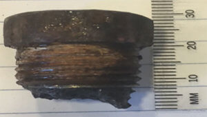
Bolt inspection.
Corrosion Morphology
“With the latest technology, FMC/TFM, the technician can fire 64 elements independently and establish tens of thousands of points/pixels in a defined area and interrogate every one by firing each crystal and the receiving responses on all the others,” explained Crawford. “It builds a massive database of responses. Once geometries are put in as part of the TFM, it can determine what each point represents. Once a scan is done, technicians can use many different configurations to gain different insights because the data has already been accumulated in the area of interest. The data can be used to configure any scan or transferred digitally to anywhere it is needed.”
Data files for TFM are well into the gigabyte realm as opposed to a standard PAUT scan, which is in the hundreds of megabytes range. Crawford noted that industry has been using this technology since 2015, but it has only just made the ASME codes this year.
Advanced Technology
Crawford sees the next wave of PAUT technology being more automated. Historically, when a weld was inspected with PAUT, technicians would review the weld scan, evaluate areas of concern, and report it. This usually was done over an extended period of time or a night shift. But automation and integration allow for all these tasks to be done in an accelerated manner to increase production, which will help improve productivity, quality, and safety.
“What we are aspiring to with PAUT is digital twinning,” said Crawford. “We would put a technician in the field who doesn’t necessarily need to have the advanced technical skills but rather applies an approved and tested application designed by a level 3 and implements it with their operability skill set. In the shop or office, another technician could monitor his or her activities and implementation by a video that would be tied through a connected device. So you could see what the on-site technician is seeing, and if there are any issues, you can relay that back to them. This allows it to be done anywhere in the world. We believe digital twinning will continue to be adopted for cost and productivity reasons.


