Magnetic Particle Inspection and Fatigue: The Impact on Probability of Detection

Not even the most advanced non-destructive testing (NDT) methods, including Magnetic Particle Inspection (MPI), are foolproof. Regardless of which NDT technique is used to evaluate a material, not all defects will be found. That being said, experienced NDT technicians can get extremely accurate results when they are aware of conditions that may impact the detection of flaws. For instance, a significant factor that can impact the probability of detection (POD) when using Magnetic Particle Inspection, or MPI testing, is fatigue.

Let’s take a look at Magnetic Particle Inspection and how fatigue impacts MPI testing.

What is Magnetic Particle Inspection?
How does fatigue impact the POD for Magnetic Particle Inspection?
How to increase the probability of detection with MPI testing

What is Magnetic Particle Inspection?

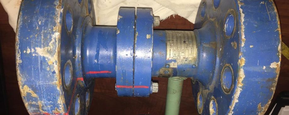
Magnetic Particle Inspection is a type of non-destructive testing. It is used to detect flaws on the surface or near the surface of ferromagnetic materials, such as iron and steel.

MPI testing is especially useful for detecting minor imperfections. This includes pores, cracks and other discontinuities. As a result, this NDT method is often used in welding inspections.

The benefits of Magnetic Particle Inspection include quick testing and immediate results. As well, this NDT method has the ability to detect flaws in materials with irregular shapes. Above all, MPI testing provides great defect resolution.

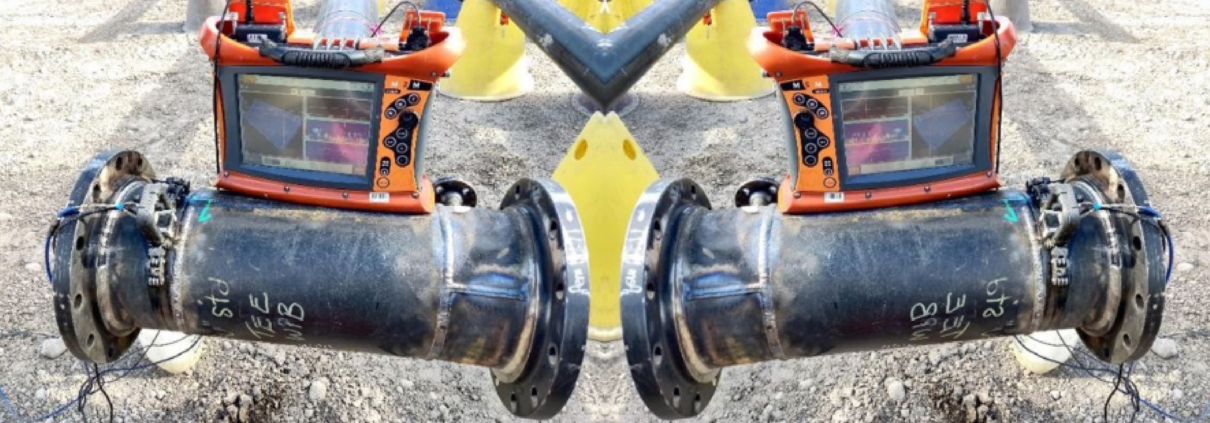
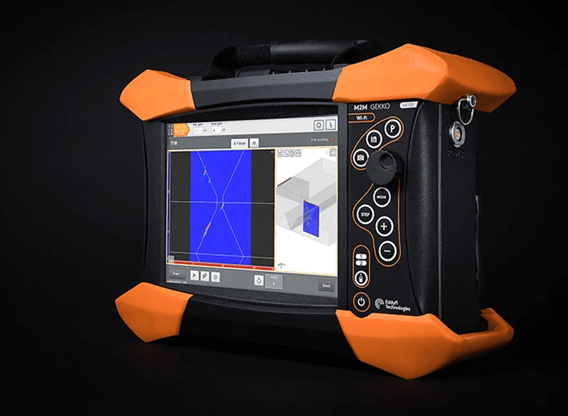
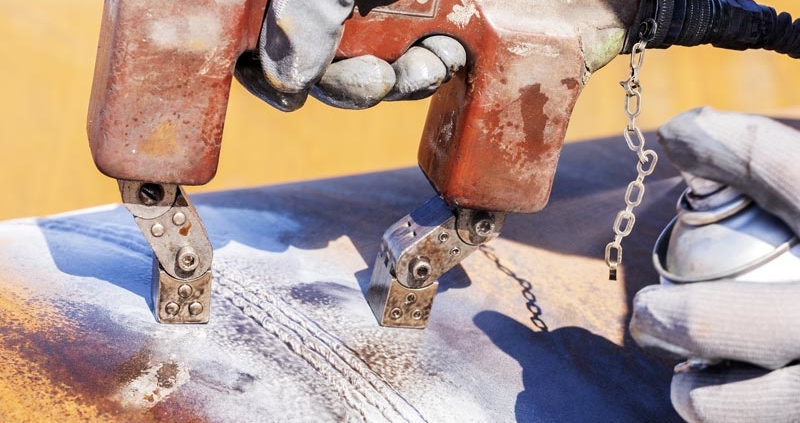
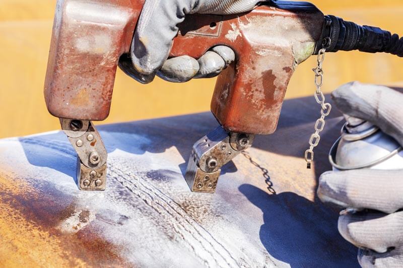
MPI testing can be conducted using several different techniques. One of the most common types of Magnetic Particle Inspection is the Yoke technique. This technique uses a portable hand-held device with an AC/DC or permanent Yoke to magnetize a material. The Yoke technique is versatile and relatively inexpensive to employ.


How is the MPI test carried out?

Magnetic Particle Inspection is conducted using several steps:

  1. Clean the surface of the material.
  2. Create a magnetic field in the material.
  3. Apply magnetic particles to the surface of the material.
  4. Remove any excess magnetic particles to uncover indications (shown by particle groupings).
  5. Clean and demagnetize the part, if necessary.

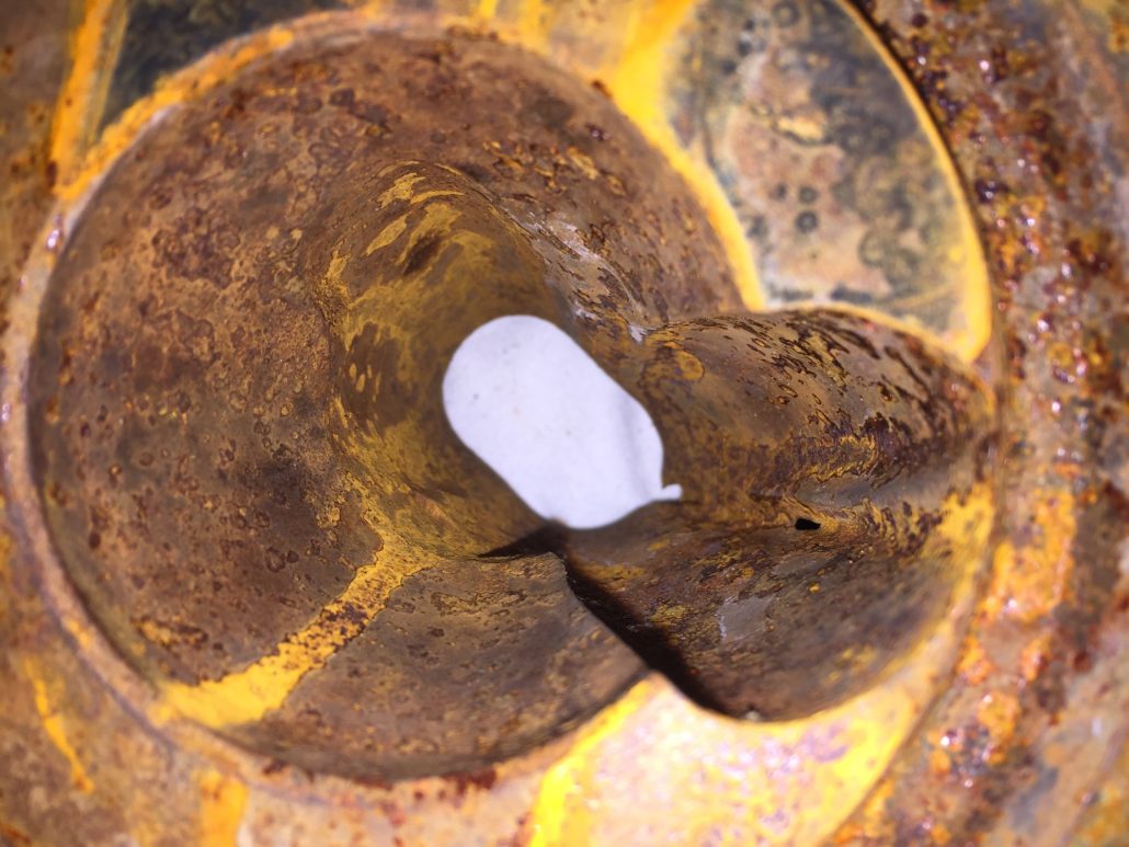
Detecting indications is straightforward in some cases. However, the probability of detection using MPI testing can become more difficult if a material has experienced fatigue.

How does fatigue impact the POD for Magnetic Particle Inspection?

Work hardening and fatigue are caused by physical processes and deformations imposed on a metal. For example:

  • Plastic deformation
  • Welding activities
  • Repeated stress and strain on the material

As mild steel experiences work hardening and fatigue, the magnetic properties of the steel change. Let’s take a look at the kinds of changes you can expect.

Property Changes Due to Fatigue

When metal becomes fatigued, three significant properties change.

  1. Coercivity Increases – the metal becomes more resistant to changes in magnetization.
  2. Remanence Decreases – after the magnetizing force is removed, very little magnetism remains.
  3. Permeability (μ) Decreases – fatigued metal becomes more difficult to magnetize.

When discussing Permeability, it’s important to note that Permeability (µ) is a ratio – a function of B and H. That is, B = µH, where B = flux density in Gauss and H = magnetizing force in Oersteds. So, when μ decreases, the amount of magnetizing force remains the same and the codes still mandate a 30 Oersted value for B. H for AC yokes is fixed. As a result, there is only physical spacing to reduce magnetizing force. 

This being said, it is important to be cognizant of the variables in order to get a result and maintain probability of Detection. B is generally overstated in the codes to a value that is three times that necessary. This results in spurious indications and a low probability of detection for Yoke MPI (i.e. around 44%).

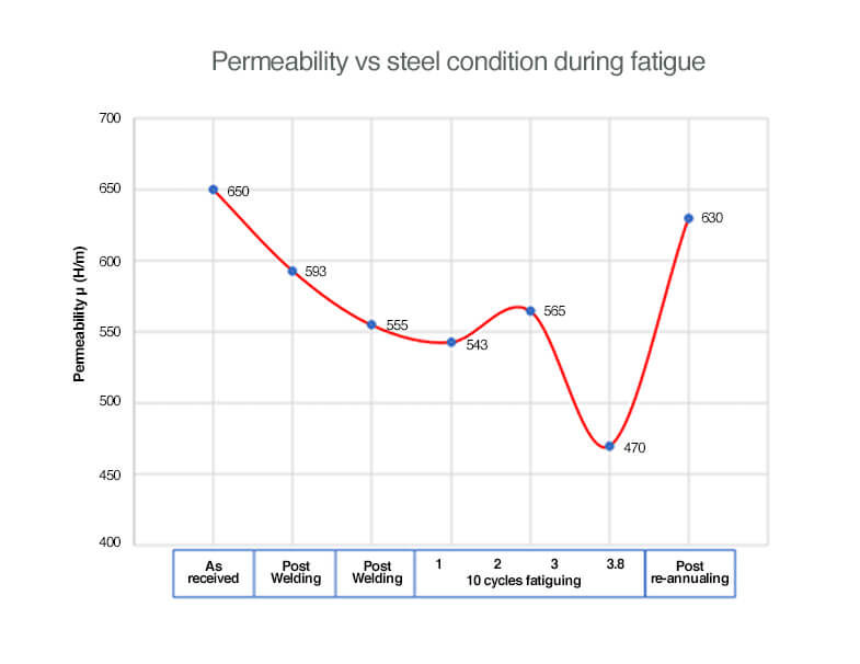
To further illustrate the extent to which fatigue affects permeability, we’ve provided a visual representation below. What you’ll notice in this diagram is that the permeability of a cracked or fatigued material is approximately 30% less than the material in its original state.

When it comes to Magnetic Particle Inspection, changes in permeability have the most significant impact on POD.

But how does permeability impact the probability of detection when using MPI testing? Let’s take a look.

Impacts of Decreased Permeability on Magnetic Particle Inspection

Decreased permeability results in a lower probability of detection when using Magnetic Particle Inspection. More specifically, POD decreases because MPI testing using a permanent magnet (like that used with the permanent Yoke technique) does not allow the NDT technician to control magnetic current. As a result, the inspector may reach saturation levels, even though the material is not magnetic enough to accurately detect flaws. Overall, decreased permeability makes it difficult to effectively uncover indications, especially those that are not large or surface breaking.

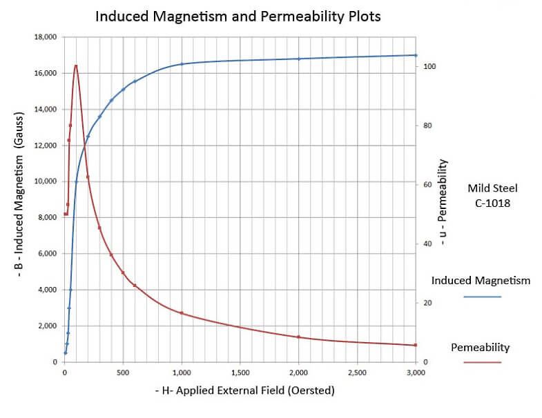
The graph below demonstrates the relationship between permeability and induced magnetism based on the strength of the external magnetic field that is applied.


The probability of detecting indications with MPI testing is especially low when evaluating fatigued materials using the AC/DC or permanent Yoke technique. This is because the technique does not allow the NDT technician to control the amount of magnetization. Rather, the AC/DC or permanent Yoke technique is a one-size-fits-all method of testing.

In addition, welded and fatigued materials exhibit variances in permeability. In other words, different areas of the material (e.g. parent material, heat-affected zone, weld) will have different permeability values. Again, because it is a one-size-fits-all method, the AC/DC or permanent Yoke technique does not lend well to testing materials with varying permeability. However, there are ways to improve the probability of detection when using MPI testing.

How to increase the probability of detection with MPI Testing

While the POD for Yoke MPI testing is low, other Magnetic Particle Inspection techniques offer a higher probability of detection. In particular, MPI testing techniques that allow for control over the magnetizing force (i.e. current control) have the best probability of detection.

MPI Techniques

Several common techniques are used to induce magnetization when employing Magnetic Particle Inspection. These include:

  • Prods magnetization
  • Longitudinal magnetization
  • Circular magnetization
  • Yoke magnetization
  • Multi-vector magnetization

Of these MPI testing techniques, the ones that allow for the most control over magnetic current will have the highest probability of detection for fatigued materials.

In addition to employing a more reliable technique when fatigue is present, NDT technicians who are aware of the impacts of fatigue and changes in permeability can use this knowledge to offer better results in the field. Leading NDT companies, like Buffalo Inspections, employ knowledgeable technicians who are familiar with the implications of magnetic physics and can ensure the best probability of detection.

Get the Most Reliable NDT Results with Buffalo Inspections

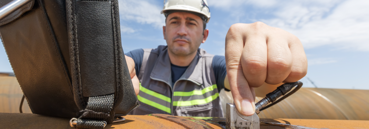
The experienced NDT technicians at Buffalo Inspections provide the most detailed and reliable testing possible. Our highly trained technicians have extensive experience in the field and provide accurate testing using state-of-the-art NDT inspection technology.

For more information on Magnetic Particle Inspection and other advanced non-destructive testing methods, contact Buffalo today.

Welding Inspection Technology: The Latest in the Non-Destructive Testing of Welds

Welding is inspected using many different non-destructive testing methods. However, some of these inspection methods are more accurate and comprehensive than others. Thanks to advancements in technology, welding inspection technology has come a long way in recent years. New technology allows welding inspectors to provide results faster and more economically with greater accuracy and detail.

Let’s take a look at some of the advanced welding inspection technology that makes this possible.

Latest welding inspection technology

Choosing a non-destructive testing company for weld inspections

The Latest in Welding Inspection Technology

There are four key technologies that have helped to improve welding inspection.

These advancements in welding inspection technology offer many benefits. Therefore, when working with a non-destructive testing company that employs these advanced techniques and tools, organizations will benefit from:

  • Increased productivity
  • Cost savings
  • Higher quality inspections

Phased Array Ultrasonic Technology (PAUT)

What is PAUT?

Phased array ultrasonic testing, or PAUT, is a form of ultrasonic weld inspection. PAUT uses a single array of transducers to employ various ultrasonic beams at different angles and focal lengths. Multiple elements are pulsed in a patterned sequence. This allows specialized software to control the angle and focus of each beam, resulting in a more detailed scan.

Phased array ultrasonic testing capabilities

PAUT accurately detects various flaws and defects. As a result of its ability to evaluate materials and equipment from various angles, it is extremely effective for testing assets with complex structures.

Phased array ultrasonic testing is particularly well-suited for weld inspection. This welding inspection technology can detect flaws such as:

  • Lack of sidewall fusion, root penetration and root fusion
  • Porosity, etc.

What are the benefits of phased array ultrasonic technology?

Phased array ultrasonic testing offers several benefits for welding inspection. This is due to its ability to use multiple elements to direct and focus beams from a single piece of equipment.

The benefits of PAUT include:

  • Ability to inspect complex assets with greater ease and in less time
  • Increased probability of flaw detection in welds
  • Improved ability to determine the size of a defect
  • Enhanced accuracy and ability to specify the exact location of a flaw
  • Higher resolution and more detailed results
  • Ability to record data and images for review in the future

Time of Flight Diffraction (TOFD)

What is TOFD?

Similar to PAUT, TOFD is an ultrasonic testing technique. Time of flight diffraction uses high and low amplitude sound waves to detect flaws. When they come in contact with a flaw, these sound waves are diffracted. Some waves scatter, while others return to the receiving probe. TOFD technology measures the time it takes for these sound waves to be emitted and returned. The characteristics of the flaw are determined using this information.

TOFD capabilities

Time of flight diffraction is best for detecting and determining the size of flaws that are below the surface of a material. TOFD can also detect small flaws near the surface. However, this is a much more difficult task.

TOFD is effective for welding and corrosion inspection. This advanced welding inspection technology is highly reliable. It can also be used for pre-service and in-service testing.

What are the benefits of TOFD for welding inspection?

There are several benefits of TOFD:

  • Reliable detection and sizing of welding flaws
  • Fast
  • Economical
  • Provides recorded data for future review and reference

Total Focus Method (TFM) Technology

What is TFM?

The total focus method (TFM) is used in conjunction with phased array ultrasonic testing. Essentially, the TFM evaluates ultrasonic testing results in a more sophisticated fashion.

TFM requires the use of a full matrix capture (FMC). With FMC, each probe emits just one signal but receives every returning signal. This data is recorded in a matrix. The TFM algorithm then uses this matrix to create high-resolution images.

Total focus method capabilities

TFM is ideal for locating small flaws in various types of materials. This method is also useful for inspecting extremely thick components, welds, and detecting corrosion.

TFM and the M2M Gekko

The M2M Gekko is a portable flaw detector that combines PAUT and TOFD with advanced TFM technology. As a result, this advanced welding inspection technology is versatile and offers high-quality imaging and extreme accuracy. Moreover, it allows non-destructive testing companies, like Buffalo Inspections, to conduct TFM inspections in the field.

What are the benefits of the TFM?

The total focus method has many benefits, including:

  • Offers the ability to thoroughly inspect various types of equipment and materials
  • Ability to detect tiny flaws, even in materials that are hard to inspect
  • Detailed results
  • Comprehensive 3D imaging
  • A single probe position can capture results from a large area

Laser-Induced Breakdown Spectroscopy (LIBS)

How does LIBS work?

This welding inspection technology employs a handheld LIBS analyzer, like the Z-300, to capture information about the atomic makeup of a material. The laser-induced breakdown spectroscopy analyzer uses highly focused laser pulses to create plasma on the surface of a material. As the atoms in the plasma return to their initial state, they discharge characteristic wavelengths of light. Subsequently, a built-in processor evaluates these wavelengths to effectively determine the elemental chemistry of the material.

Laser-Induced Breakdown Spectroscopy capabilities

This technique can accurately identify materials used in piping, pressure vessels, finished welds and more. As a result, the oil and gas industry commonly employs LIBS technology.

What are the advantages of Laser-Induced Breakdown Spectroscopy?

LIBS offers several advantages including:

  • Versatility – LIBS can characterize solids, gases and liquids
  • Simplicity – a handheld analyzer is easy to use and carries out the process in a single step
  • Offers the ability to identify multiple elements through a single analysis
  • Fast and convenient

In addition to the many benefits of laser-induced breakdown spectroscopy, the Z-300 handheld analyzer offers benefits of its own. Most notably, is the only handheld in the world that is capable of providing in-field analysis of elements like Li, Be, C, F, B, etc. As a result, it can provide more accurate and detailed inspection results.

Non-Destructive Testing Companies & Welding Inspection Technology

When working with a non-destructive testing company to evaluate welds, ensure that they use the latest welding inspection technology and methods. This will guarantee that you receive the most accurate inspection.

Buffalo Inspections employs the most advanced welding inspection technology available. This ensures the best possible results at the lowest possible price. As well, our NDT technicians are highly trained and experienced. Most importantly, they are well-versed in the latest NDT technologies. As a result, Buffalo provides the most detailed and reliable inspections possible.

Contact Buffalo Inspections today to learn more about our welding inspection technology and the value we can provide your organization.

Use of digital twinning in the field

Digital Twinning and Enterprise Systems for the NDT Industry

2020 has come and gone and whilst most people are glad to see the back of it, there is and was much to be learned from it on the inspection front. While Zoom, Teams, Skype and Face Timing have become standard practices for business; digital twinning, remote inspection oversight, analysis and enterprise reporting within the inspection industry have not. While they are technologically possible, we have not been able to fully apply them during this transitional time due to legacy interpretations and habits not evolving.

What is Digital Twinning?

Digital Twinning (DT) for the purposes of this article, is the term given to a digital replication of the systems and devices used for inspection. It essentially means that an inspection can be done in Alberta and be directly linked in real-time to a screen anywhere in the world.

Benefits of Digital Twinning

The direct benefits of DT are that you can have one level 3 controlling up to 4 technicians, and potentially more, while providing analysis and reporting without having to be deployed to the site.

Digital Twinning and NDT

To this day, there are words in our codes that state “Direct oversight” must be in place for all inspections done by anyone other than a level 2 or 3 technician. National Standards and Company specifications mandate that inspections must be done by a level 2 or 3. Not much has changed on the inspection front within these documents that would allow for DT, Cloud, and enterprise technologies to be fully implemented. Bearing in mind that the legacy of many Standards and Codes, was based upon analogue technology with a low Probability of Detection, (in the order of 50% for manual shear wave), so “direct oversight” in the literal sense was essential and supported the codes and standards intent.

Cost Savings and Improved Efficiency

This year’s impact on business has resulted in a lot of clients asking for discounts and reduced pricing for inspection scopes. The lesson learned is that manageable price reductions must be correlated to improved or modified inspection practices, so the commercial viability continues to allow a solid and beneficial business relationship and maintains quality and consistency of results. In short, standards and specs need to come up to speed on newer technology and the digital realm, to improve efficiency, and allow productivity increases wherever possible, whilst maintaining the consistency and quality of the inspection task.

Digitization in the NDT Industry

After 40 years in this industry, I have seen more advancement in the last 5 years than I have in the previous 35. What has enabled this? A combination of software and hardware advances, reductions in hardware prices and a global cooperative that has enabled best practices to be standardized; plus, internet speed, interconnectivity, and cloud accessibility. The transition to the digital world has arrived and most of the equipment can now produce images from collected data and transmit it to the cloud for ease of access and analysis from anywhere. Data can be extracted in many forms and combinations to enhance and support this analysis.

Digitization has arrived for radiography (RT), ultrasonics (UT), eddy current (EC), visual testing (VT) and many other inspection disciplines. The ability to simply deploy and operate digital inspection equipment under the supervision of a qualified individual, through body cameras, digital twinning, and audio, while using developed applications programmed into the equipment to baseline key variables, is common sense. It also fulfills the direct oversight mandate from a 21st-century perspective. Interestingly, large projects who are raising significant amounts of capital are increasingly being told that digitization is a strategic necessity.

Implementing Digital Inspection Equipment

The key to supporting these initiatives is the training of technicians from a very early stage. When I came into this industry in the 80’s you did not really get to touch advanced inspection tools until you had all the academic tools to enable you, plus years of experience. What has changed?  Equipment has become more of an operability exercise than a full-on in-process analysis task, as most of the calculations and historically cerebral activities occur within the equipment itself.

Buffalo Examines the Viability of Digital Twinning

Our company’s research program for advanced UT (PAUT, TFM, Plane Wave) has undertaken several experiments to identify technical uncertainties with digital twinning and have identified data, equipment, and practical issues that supervision needs to be alert to.

What we did find was the innate ability of the younger technicians to operate newer digital equipment and quickly fathom out the operability elements that allow field deployment. The interface is key to this and the time and effort employed by software groups in improving this has been incredibly successful, based upon our findings. Bear in mind, that having a level 3 or highly experienced Level 2 overseeing this training is paramount to its success, as there are many nuances that need to be covered during training, related to key variables and how and when the application adjustments need to be considered.

The wonderful thing about digital technologies is once you have refined an application for a specified task it can be easily deployed for small or large quantities and you get imagery and data to support and verify all key variables. However, the geometric nuances and indeterminate signal responses are what require training and supervisory input to ensure a consistent quality of results and analysis.

During our experimentation, there were key variables such as hi/lo locations, material thickness variances and other geometric anomalies that needed to be documented to allow high confidence remote analysis. When there was still concern about an indication, application modifications or changes to the technique were required; this was part of the technician’s training focus to ensure competency in operating remotely with the equipment at hand. This was performed all while under the remote supervision of the Level 3.

Digital Twinning Training

Most digital equipment provides a 2D image and in many cases can also be used to render 3D images. This imagery is part of the learnings that have enabled the use of uncertified trainees to be successful in the deployment of advanced digital NDT equipment with Digital twinning.   Pattern recognition is the quickest and best way to teach, and the quality and accuracy of image formation on modern equipment is superb and very accurate if the correct info is provided.   Good technicians are prone to ask questions and are inquisitive, which helps the Level 3 in analysis.

While I have used advanced UT as the primary reference in this document to date, I have done so given it has the most variables to consider and was the focus of our research program.   Other disciplines such as RT can digitize in video form or image form as can Eddy current, ACFM, and visual through laser or video scanning, and their variable numbers tend to be way less than advanced UT, so technically and assumptively, that means that they should be easier to deploy.

Enterprise Systems

The client/customer pays for a report that evaluates the item inspected against a code or standard and which is verified or signed by a competent person. That means that in parallel with digital inspection technologies we need an enterprise reporting system that can support data, imagery, and the direct conversion of essential variable info onto the report. Additionally, it must be signed by a correctly certified technician for it to have any value.

The solution is an enterprise system with offline and online capabilities that enable the transfer of data through the cloud or directly, that can be incorporated into a final document in any form (numeric, text, image, or video). This can then be accessed by the customer or any approved entity that needs to review or receive it. These systems are available commercially, or in my company’s case, we created one tailored for our needs (Connex). Over the last 10 years, we have been updating its capabilities continuously to support the newer technologies and the parallel commercial elements that support all inspection activities.

Enterprise System Challenges

The one challenge that currently exists is data file size in the case of advanced UT or video. Should the client want a complete copy of the data file it can sometimes run up to 4 gigabytes in size (technique dependent). When only a report with still images is needed, then file size is easily accommodated. Remember that anything is possible if enough time, intelligence, and money is available, but we are always constrained by the commercial necessities presented.

We are currently involved with a multinational partner in the digital RT sector where we are trying to place a fully marked-up radiographic image onto the RT report (all digitally of course) within the enterprise system. This research has a guaranteed outcome with the existing technology we have. It can also be replicated across all disciplines.

An additional and noteworthy concern of an enterprise system is ensuring the system structure is secure enough to guarantee the clients’ outcomes and give them a high level of confidence in the quality of the outputs. These concerns are specific to each client but are driven by good process and practices.

The Future of NDT

How we select candidates to deploy these transformational technologies is a science in itself; trainees need to be motivated to not only execute inspection in the field, with all its incumbent challenges but to be scholarly in the pursuit of knowledge associated with these challenges. Our experience with this element of the digital transformation has been interesting. Younger people interested in inspection are not keen on sitting in classrooms for extended periods of time, they want to be fully immersed and be earning revenue as soon as possible, then progressively learn as they go. The digital world allows this with online learning and as long as they have a committed mentor to learn from, they can quickly become productive employees.

Our experience with using these methods has demonstrated savings of up to 40% against the current inspection protocols being deployed. It is only a matter of time and desire before we are all on the same page.


Andrew Crawford BSc, BTech, PG Dip NDT, CGSB L3
TQMS, Buffalo Inspection Services

NDT inspection

NDT Inspection Technology: What’s New and Leading-Edge in 2020

NDT inspection technology, including training and tools, is continuously evolving.

With changes in government regulations, innovations in technology and the ever-changing needs of industries requiring surface and subsurface analysis, non-destructive testing continues to evolve to ensure the safety, productivity, and integrity of materials, products, and structures.

Interested in knowing more about what’s new and leading-edge in non-destructive testing (NDT)? This article will cover:

Why NDT is important
The advantages of NDT
What’s new in NDT training
What’s new in NDT technology
Pipeline inspection improvements

Why NDT is important

Non-destructive testing is vital for the timely detection of faults in products, materials, and equipment. If left undetected, defects and flaws can result in expensive and premature repairs or replacements. Unplanned shutdowns and failures can also result and have devastating health, safety, and economic impacts.

For pipelines, oil and gas, mining, lifting and industrial construction equipment, and tubing, NDT functions as quality assurance, ensuring the reliability and expected lifetime of equipment and materials is upheld.

Regular testing allows engineers to determine the current lifecycle stage of an asset and to proactively plan maintenance, repairs, or replacements. Regular inspections also ensure that catastrophic failures of your business/operational assets do not occur, potentially resulting in lengthy and costly downtime. Besides, routine testing ensures adherence to government regulations and standards, as well as the health and safety of your workforce and the environment.

Overall, NDT:

  • Prevents accidents
  • Reduces repair and replacement costs
  • Improves reliability of assets
  • Ensures adherence to regulations and policies


What are the advantages of NDT?

Non-destructive testing is ideal because it allows for the inspection of equipment, materials, and structures without the need to worry about downtime or damage.

NDT can save time and money by identifying problems early – before expensive repairs or replacements are needed.

What’s new in non-destructive testing

Advancements in technology and changes to government regulations and policies are continuously driving innovation in non-destructive testing. These changes affect all aspects of NDT, including training, inspection, and technology. The result – new and innovative methods and strategies.

NDT has come a long way since its origins. Simple VT has now evolved with the digital world, resulting in digital outputs, including 3D imaging and cloud connectivity that allows for remote testing and analysis.

NDT Training

NDT inspection technology and its applications are continuously improving and evolving. Inspection technology, equipment, and the services offered by inspection providers are ever-changing, including advancements in training and techniques.

Buffalo Inspection Services, for instance, recently implemented a Personal Certification in Non-Destructive Testing (PCN) course using Gekko and Mantis technology. This training is revolutionary, making Buffalo the first NDT company in North America to host PCN Certification on Gekko PAUT technology and the only non-union NDT inspection services provider in Western Canada with qualified PCN technicians.

NDT Inspection Technology

Advancements in technology drive change in non-destructive testing. As a result, hardware and software enhancements are continuously developed to improve testing and analysis.

Below are some of the most recent advancements that have been made in NDT technology:

The GEKKO

Buffalo NDT Inspectors uses the M2M Gekko for PAUT inspections.

The M2M Gekko is one of the most advanced and reliable options for Total Focusing Method (TFM) testing. The only unit that supports a 3-axis encoder for TFM, the Gekko is also the first system able to produce matrix arrays and perform TFM in real-time.

As the most versatile and advanced PAUT field unit, the Gekko can cover a wide range of inspections, and, recently, a new generation of the Gekko was released, with various ground-breaking advancements introduced.

Improvements to the new generation of the Gekko include:

  • Hardware – increased speed and channel sensitivity, longer battery life (up to 6 hours), improved touchscreen functionality (e.g. touchscreen can be used with gloves)
  • Data management – new USB 3.0 connector for rapid file transfer and wireless data or screen sharing, IP68 LEMO encoder connector for compatibility with most scanners
  • Software – the release of new Capture 3.1 software

Capture 3.1 software

The release of Capture 3.1 has brought many improvements to ergonomy, analysis, and TFM tools and options. The new advanced analysis tools offered by Capture 3.1 improve productivity and increase the quality of research and reporting, resulting in more efficient and reliable testing.

The new tools added to Capture 3.1 include:

  • Auto-sizing – for a quick analysis of whether an indication is critical
  • C-scan stitching – for inspections that require more than one file
  • Full 3D exporting
  • Improved indicators

TFM

The Total Focusing Method has come a long way since its inception. In 2013, portable TMF revolutionized non-destructive testing. Since then, TMF has seen significant changes to scan speed, the number of TFM options available on the market, and to code. These advancements have allowed TMF to remain one of the best and most reliable techniques for NDT.

  • TMF options on the market
    2013 – 1 TFM option
    2020 – more than 10 TFM options
  • Scan speed
    2013 – ¼ inch per second
    2020 – more than 4 inches per second
  • Code
    2013 – No TFM code
    2020 – Code-compliant

Along with the recent release of Capture 3.1 software, a new TFM method called Plane Wave Imaging (PWI) has also been introduced.

Plane Wave Imaging

PWI, introduced by Eddyfi Technologies, is a new data acquisition technique for TFM. This technique is conducted by first firing all the elements of the array concurrently on several different angles, with elementary signals received on all of the elements. After this initial process, a typical TFM is performed. The final result is a matrix containing M x N (number of angles x number of elements) elementary A-scans.

PWI - Plane Wave Imaging demonstration for NDT Inspections

The advantages of this new method include:

  • Improved productivity – PWI is able to maintain the spatial resolution offered by other TFM methods (e.g. FMC) while increasing scanning speed.
  • Increased sensitivity – depending on the number of angles used, PWI can offer an increase in sensitivity, resulting in the detection of smaller indications.


Pipeline inspection improvements

These new and leading-edge advancements in NDT allow for regular, comprehensive, accurate, and economical testing. The efficient and effective testing provided by a combination of this state-of-the-art technology ensures the safety and utility of large pipelines like the Transmountain.

Combining PAUT / TOFD and conventional UT with advancements like TFM, the Gekko is particularly useful for pipeline inspection in Alberta.

Radiography (x-ray inspection) and UT are commonly used; however, Phased Array Ultrasonic Testing (PAUT) offers several advantages for pipeline inspection. These advantages include NO:

  • Radiation
  • Risk
  • Additional licensing necessary

With the ability to detect manufacturing flaws, corrosion, cracking, erosion, parent metal flaws, and more in pipelines, all while in-service, regular non-destructive testing ensures cost efficiency, environmental and public safety, and reliable, long-term performance.

Want to discuss NDT pipeline inspection for your company? Contact Buffalo today.

3D images using the appropriate software

What is Phased Array Ultrasonic Testing

With PAUT, the technician actually gets images of the scanned areas in A, B, C, and D forms, which then can be generated into 3D images using the appropriate software.

What if ultrasonic results were presented in picture form instead of a written report? What if 3D images of welds were available for a welder to review at any time? What if all this data could be kept in digital form? And what if your confidence for the probability of detection (POD) soared from 50 percent to over 90 percent?

These are the questions that Andrew Crawford, TQMS manager for Buffalo Inspection Services in Edmonton, posed at his presentation during this year’s CanWeld event as he introduced the audience to the latest in phased array technology.

Non-destructive testing (NDT) has been an essential component for the production of quality parts in the fabricating and welding sector for decades. For general methods of testing, including eddy current (ET), magnetic particle (MT), liquid penetrant (PT), radiographic (RT), ultrasonic (UT), and visual testing (VT), the physics behind them hasn’t changed significantly since their inception into the market. However, NDT has become more advanced through innovation and technology trends. The hardware for these methods will become more affordable, but it is the software that will determine functionality.

New ways to collect and interpret data will in time push methods to their limits, eventually phasing them out to make way for advanced methods. Crawford used the example of how shear wave single crystal technology, which has been around since the 1950s and still being certified in Canada, is slowly being phased out by more advanced technology like phased array ultrasonic testing (PAUT).

PAUT

PAUT

PAUT is a newer method of NDT that became commercially available in the 1990s in a portable form, after the release of Windows 3.1, and evolved from the traditional UT method of single-crystal technology combined with software and computing power to allow multiple crystals to work together to form focal laws.

With traditional manual UT, a technician manipulates the probe around a weld to complete the scan. Then, using his body of knowledge and pattern recognition skills concurrently with the scanning activity, he interprets the scan.

“The probability of detection for manual UT is around 50 percent,” said Crawford. “Moving into PAUT, the probability of detection dramatically increases to well above 80 percent. Using the total focusing methods (TFM), it’s approaching 95 percent.”

With PAUT, the technician actually gets images of the scanned areas in A, B, C, and D forms, which then can be generated into 3D images using the appropriate software. The different image forms provide a comprehensive perspective in 2D versus one single A-scan electronic trace as has been traditionally provided.

The UT technician can now see a picture of what the beam is seeing. This technology still requires some interpretation, analysis, and human intervention. Having a strong understanding of the physics, equipment operation, and welding details will help technicians interpret any anomalies indicated.

“With PAUT, we are still using piezoelectric transducers, but with the current algorithms we can develop all manner of focal laws and applications,” said Crawford. “The end result of all of these improvements is the easier analysis and less interpretation of A-scan patterns, better accuracy, resolution, and, of course, imagery.”

PAUT technology scans

Advancements in PAUT technology have resulted in easier analysis and less interpretation of A-scan patterns, better accuracy, resolution, and 3D imagery.

Remembering that ultrasonic inspection is stochastic in nature, the more data we have, the more accuracy we can determine.

There are various methods of data acquisition, including total focusing method (TFM), matrix arrays, sectoral scanning, electronic scanning, and multi-salvo techniques. Full matrix capture (FMC) and TFM, the most comprehensive techniques, did not become a portable option until 2014 when computing power became adequate. Prior, it was an offline function only.

“The technology has evolved to allow for high-temperature in-service inspection,” said Crawford. “The future, however, is in the software. Hardware will become standardized, but the software and user interface elements will be the core advancements going forward. The current expansion of PAUT, TOFD, and FMC/TFM will inevitably result in the further evolution of these technologies, resulting in benefits in resolution and accuracy, along with applications.”

FMC/TFM is currently the highest level of commercially available phased array technology. This method offers inherently higher resolution, accommodates mode conversions, and gives high-resolution imagery of indications and profile morphology.

Weld Inspection

PAUT is especially suited for weld inspection. The technician can simply put the weld profile in the program along with dimensional offset info, and once it’s scanned, it will show the exact location of an indication, which from a welding perspective tells the welding engineer where problems are occurring.

“If it’s a fracture mechanics-based acceptance criteria, this will have higher accuracy and allow the welder to understand where they are making mistakes,” said Crawford. “From an engineering perspective, it provides a lot more information to inform future designs and make smarter decisions on whether defects will cause problems or not.”

Electronic scanning is primarily used for scanning geometric surfaces on weld profiles or at fixed depths. This method deploys all of the available beams to concurrently hit a geometric profile or a portion of that profile at a specific angle or position if there are areas of concern. With PAUT, the technician has the flexibility to use from four to 64 elements; these numbers could potentially grow in the future, depending on the need.

“From a simple weld inspection standpoint, our obligations are to do a full geometric and volumetric inspection; anything less is considered an incomplete inspection,” said Crawford.

Beyond welding, PAUT is also being used for corrosion assessment as well as testing on complex geometries, flange face corrosion, bolts, pulsation dampers, and anything with a configuration that is not traditional or uniform. The technician performs a blanket scan and the software is able to stitch it all together to end up with an appropriate view, which when combined within the software, essentially provides a 3D image.

PAUT, particularly for weld inspection and corrosion detection, offers a high probability of detection that can discriminate defects versus geometric ghosting. Having all the data and images also provides an auditable trail.

Bolt inspection.

Bolt inspection.

Corrosion Morphology

“With the latest technology, FMC/TFM, the technician can fire 64 elements independently and establish tens of thousands of points/pixels in a defined area and interrogate every one by firing each crystal and the receiving responses on all the others,” explained Crawford. “It builds a massive database of responses. Once geometries are put in as part of the TFM, it can determine what each point represents. Once a scan is done, technicians can use many different configurations to gain different insights because the data has already been accumulated in the area of interest. The data can be used to configure any scan or transferred digitally to anywhere it is needed.”

Data files for TFM are well into the gigabyte realm as opposed to a standard PAUT scan, which is in the hundreds of megabytes range. Crawford noted that industry has been using this technology since 2015, but it has only just made the ASME codes this year.

Advanced Technology

Crawford sees the next wave of PAUT technology being more automated. Historically, when a weld was inspected with PAUT, technicians would review the weld scan, evaluate areas of concern, and report it. This usually was done over an extended period of time or a night shift. But automation and integration allow for all these tasks to be done in an accelerated manner to increase production, which will help improve productivity, quality, and safety.

“What we are aspiring to with PAUT is digital twinning,” said Crawford. “We would put a technician in the field who doesn’t necessarily need to have the advanced technical skills but rather applies an approved and tested application designed by a level 3 and implements it with their operability skill set. In the shop or office, another technician could monitor his or her activities and implementation by a video that would be tied through a connected device. So you could see what the on-site technician is seeing, and if there are any issues, you can relay that back to them. This allows it to be done anywhere in the world. We believe digital twinning will continue to be adopted for cost and productivity reasons.

Non-destructive testing specialist

How to Become a Non-Destructive Testing Specialist in Edmonton

If you like challenging situations that require attention to detail and problem-solving, you’re a prime candidate for a non-destructive testing specialist. Following is how to become a non-distributive testing specialist position in Edmonton.


General requirements


Most positions need as a minimum a high school diploma or GED equivalent, a college education in Material science or Welding will reduce the necessary time required to certify yourself in NDT and give you the key materials knowledge necessary for advancement.
You can go from a level 1 technician to a Level 3 technician and up to a MSc in NDT or anywhere in between, depending on experience and education.


Skills required


As a non-destructive testing specialist, you need an understanding of materials, corrosion and operating equipment to recognize the nature of and potential for problems. A good technician must be able to identify the type of problems that may already be occurring.
Testing different materials in different situations requires training and experience to see specific types of defects and their extent. You must be able to detect and accurately size indications with the potential for harm.
As with almost any position, you must be able to take direction both verbally and in writing and apply reasoning to them. A non-destructive testing specialist uses his or her skills to offer clear answers to questions.

Good vision and the ability to differentiate between colors, including shade and brightness are key. You must also be in good physical condition; specialized rope access NDT technicians have advanced mountain climbing training. Dexterity is important to ensure consistent inspection application with the various technologies. The ability to think quickly with strong reasoning skills are key for all non-destructive testing specialists.


Education levels


Over half of all non-destructive testing specialists generally have a high school diploma. Almost 30% have an associate degree, while only 7% have a bachelor’s degree.

All non-destructive testing specialists need certification from an institutional body such as:

  • CGSB Canada’s National Non-Destructive Testing Certification Body.
  • Personal Certification Network (PCN) and The Certification scheme for Welding inspection Personnel (CSWIP)
  • ASNT American Society of NDT

This ensures you can work anywhere and cover the greatest amount of client needs.

You can get certain certifications from these bodies in multiple disciplines:

  • Radiography
  • Ultrasonics (Phased Array, Time of Flight Diffraction, Guided wave etc.…)
  • Magnetic Particle Inspection
  • Dye Penetrant Inspection
  • Eddy Current Inspection

The CGSB would be your first point of contact and others could be explored and pursued from there. The CGSB will provide you with an examination guide to study for the written examinations. You must know and understand the applicable acts, regulations, standards, and safety codes.

Once you are certified, you must keep your certification current. This means renewing and re-certifying yourself every 5 years before the expiration date to keep up with changes to technology and code.


Conclusion


A career as a non-destructive testing specialist is both rewarding and essential to the overall safety of equipment and the public at large. You can find job openings by searching the internet, where you can also find more information about employers looking for technicians.

If you have the skills listed above and are willing to become certified, a non-destructive testing specialist may just be the perfect job for you. You can find everything you need for a career as a specialist on the CGSB website.

Training institutions such as NAIT and SAIT offer dedicated training as well.

TFM/PAUT Inspection

Announcing: TFM/PAUT Inspection for On-Stream Monitoring

Industry experience has shown that most companies are only able to inspect approximately 3-5% of their equipment a year. When the cost of inspection weighted against the cost of down time is incidental, cost effective approaches to inspection can be undertaken. Expensive emergency outages, the costly impact of spills on a company’s environmental reputation, or a very serious process safety event with potentially catastrophic endings can be avoided. One common theme heard is “we don’t know how to monitor {insert asset here} so we just wait until it washes out or fails”. Corrective Based Maintenance strategies like this can now be advanced to Condition Based with Buffalo’s new technology.

Through our industry experience, we have been able to assist clients in determining key locations for inspection, to enable them to pursue an online condition based assessment.

Buffalo Inspection has been utilizing cutting edge equipment, combined with best in class PCN PAUT training, to provide a complete inspection package to our clients. This isn’t a standard data collection inspection. We are in this to ensure not only the integrity of the asset, but to save our clients time, money, and headaches. Through our

industry experience, we have been able to assist clients in determining key locations for inspection, to enable them to pursue an online condition based assessment.

TFM/PAUT Inspection

We have developed inspection methods for specific client requirements such as Choke Valves, Flange Face Corrosion, Internal Current Transfer Corrosion, HDPE inspections, and an ever increasing variety of previously uninspectable situations. Conventional ultrasonic methods experience limitations that modern phased array technologies have been able to overcome. Permanent, Auditable data, has established itself as a necessity for integrity management.

Working with our clients, has allowed us to alleviate issues that hadn’t been solved for them in the past. It has also allowed clients to increase the integrity of their assets. Code minimums are exactly that, minimums, but what if it was faster, better, and cheaper, to get more? That is exactly what we at Buffalo Inspection Services are striving to provide.

NDT Certification

NDT Certification Differences

Institutional certifications and recommended practice certifications. What’s the difference?

Supplying clients with certificated technicians is essential in our industry; unfortunately, not all contractors provide the expected quality of technician. The result is that the client wants evidence that the technicians are properly qualified.
In many cases the technician holds the responsibility of passing a judgement on the acceptance or rejection of the inspected component. It is the operator through whom we depend to accurately evaluate defects and indications; if the operator is not properly knowledgeable, trained and experienced they might totally misjudge the results of NDT and reject components which are sound and capable of performing in the service. On the other hand, they might send the faulty components into service which may become a source of premature failure. In both cases the consequences are going to be adverse. In the first case the organization is going to suffer undue production losses while in the second the premature failure may lead to even bigger losses. Of no less importance is the integrity of the operator in view of his ability to provide accurate reports.
A central system of certification (per ISO 9712 and EN473) such as CGSB, PCN, CSWIP and ACCP has technicians study the relevant subject material, undertake the necessary experience and training requirements and then go to an authorized examination provider to take an independently set and invigilated examination. When they pass their exam, they are awarded a certificate of competency in that respective NDT Discipline. This can then be used by their employer or a potential employer anywhere within its jurisdictional or accepted limits. At Buffalo Inspection Services, we have chosen to support our clients and technicians with certifications that are recognized broadly as thee standard. We see this as a competitive advantage and a sustainable quality standard for our clients.
The employer still has a level of responsibility of ensuring the capability of the technician in applying their qualification (Duty of Care) to the specific work process, but this is relatively easy task compared to the qualification process. However, When the technician asserts an opinion on an inspection with an institutional certification their opinion has increased “Value at law” due to their duty of care obligations.

In the ASME system, the ASNT Recommended Practice SNT-TC-1A is the dominant certification program, it is not an institutional program but an employer-based form of certification. SNT-TC-1A is a recommended practice and not a standard, which gives the employer a certain amount of flexibility concerning the necessary requirements needed for an NDT technician pertaining to the specific NDT applied. A written practice allows discretion in the practical nature of examination, which is for all intent and purpose a positive element. However, the negative aspects of discretion give way to the temptation to provide inadequate structure and correctness to the certification process along with the relative capacity to ‘rubber stamp’ certification. Additionally, the SNT-TC-1A program has no portability for the technician and as such has no central database for verification. This has been an ongoing challenge and complaint from NDT customers for years when it comes to the overall competency of a technician. In addition to this challenge is that the technician’s opinion is inherently linked to the NDT service provider who is linked by code to the manufacturer or fabricator. Which means that a technician’s opinion has limited or no Value at Law (per code) by comparison to the employer or fabricator. Buffalo does provide our technicians with the added practical in-house oversight of an SNT exam however, we are moving towards wanting as a minimum for our technicians to have CGSB, PCN,CSWIP and ACCP as table stakes for competency.
As production demands and reliability increase, the opinion of an NDT technician has become more and more important as far as identifying and evaluating defects and indications correctly and accurately.

I remember in the Middle East years ago, when technicians came from all over the world and there was not a clear understanding of consistency in certification; for this reason and others similar, the ‘performance demonstration’ was established.
In the interim we have had API establish performance evaluation tests and more recently ASNT’s central certification program ACCP and now we have ASME coming up with their own contribution in the form of ANDE “The ASME Nondestructive examination” program. The instigator of all these performance demonstrations to identify technicians capable of finding cracking in SS welds was the Nuclear Industry.
Now, with the plethora of certification programs out there we have what appears to be a never-ending requirement for training and all its incumbent expenses. Whether this creates better technicians or not remains to be seen, but, it sure creates a scarcity of skilled personnel.
Industry needs to agree on a standard of certification that ensures competency and accuracy in the delivery of the service. CGSB, PCN, CSWIP and ACCP are the pillars of internationally recognized central certification programs and are increasingly essential for hiring and advancement at Buffalo Inspection Services, These programs should be a minimum pre-requisite to all NDT undertaken in our country.

Laptop

Buffalo Has First Paper Presented at CINDE Conference

Executive Summary

This paper documents the development of an alternative ultrasonic testing (UT) technique for examination of structural welds as per CSA W59.

The purpose of developing a new technique is to bring CSA W59 into the 21st century, allowing for modern techniques, equipment, and to provide a pathway for future development not permitted by the current 1960’s-era practices. The existing techniques were part of the 1969 edition of AWS D1.0. They were not developed from scientific principles or empirical evidence, yet have remained the “line in the sand” for structural UT in North America for nearly 50 years. Since then, exponential changes have taken place in technology and in the general UT world, yet Canadian and U.S codes have failed to keep pace. This has resulted in awkward techniques that many technicians misunderstand and circumvent. Ultimately, these outdated techniques fail to serve the purposes of repeatable and accurate inspections they propose to facilitate.

The existing fixed attenuation, or “FA” technique is shown to be based on assumptions of sound attenuation and inspection angles which do not hold up under scientific scrutiny. There is a philosophy of “one probe to rule them all” and angle-specific procedure tables which were installed to achieve consistent inspection results. However, the practices involved in limiting one’s options does not produce the consistencies intended. A new technique is presented which is similar to those used elsewhere in the UT industry. This is written as a true alternative to the existing technique, offering adapted acceptance criteria that retain the existing quality levels. Mathematical models and experimental data are presented which were used to generate the new criteria. Equivalence is also demonstrated through modeling. Variation in results is also significantly reduced.

The proposed alternative technique is under public review for inclusion in CSA W59-2018. The techniques developed in 1969 have served industry well for a very long time, but change is inevitable. To progress in a world of rapidly advancing technologies, it is important to adopt less regressive, more forward-thinking practices that can adapt and suit the needs of today.

Download the entire paper by clicking the image below:

Sa-W59 Ultrasound Inspection

Pipeline Inspection

Buffalo Inspection Services expands footprint with acquisition of Radius Inspection Services

EDMONTON, Alberta, October 1, 2014 Canada’s largest non-union Non-Destructive Examination (NDE) services provider, Buffalo Inspection Services (2005) Inc. (Buffalo Inspection Services), has acquired Radius Inspection Services (Radius), and independent owned and operated NDE company in Northeastern British Columbia, to continue its expansion into under-served locations.

Radius primary operation is strategically located in Fort St. John, British Columbia, a growth market for oil and gas and pipeline development. The acquisition provides Buffalo Inspection Services with the capability of increasing its presence in North East British Columbia working in partnership with an experienced and capable team.

Radius will operate locally as Silver Shadow Inspection Services, a Division of Buffalo Inspection Services and as a result of this deal will now be in a position to provide additional services such as Phased Array and Mainline Crawler capabilities to its clients.

The company has appointed Glen Griffiths, Regional Manager of Buffalo, to work with the existing Silver Shadow and Radius teams to lead the transition, aligning the organizations together and to integrate Buffalo’s structure that has been refined over the last 38 years.

About Buffalo Inspection Services

Buffalo Inspection Services is the largest non-union NDE company in Canada. Headquartered in Edmonton, Alberta, Buffalo has been providing NDE services primarily to the oil and gas industry across Alberta, Saskatchewan and British Columbia for the last 38 years. The company offers a complete suite of NDT services including Radiography, Mainline Gamma Crawler, Magnetic Particle, Liquid Penetrant Examination, Visual Inspection, Phased Array, Ultrasonics, Ferrite Testing, Positive Material Identification, Hardness Testing, Tubing Inspection and Time of Flight Diffraction. The acquisition brings together the teams of Buffalo Inspection and Sliver Shadow to create a 226-strong workforce comprising skilled and certified professionals.