Contact Buffalo to discuss NDT Inspections for your company.
Head Office: 3867 Roper Road Edmonton, AB T6B 3S5
Toll Free: 1.800.634.8588
Phone: 780.486.7344
Fax: 780.486.4685
At Buffalo Inspection Services, we are always looking for ways to provide significant project-cost savings and increased weld quality. With new and emerging technologies such as TFM (Total Focusing Method) and Laser Induced Breakdown Spectroscopy (LIBS), portable spark testing equipment that measures Li/Be/Boron/Carbon, being added to our advanced services and surface department. We can increase productivity, reduce overall cost, and provide the highest quality inspections possible to our clients.
The new M2M GEKKO architecture fits perfectly within our advanced services ecosystem as it allows for comprehensive inspection of a broad range of equipment and materials. The Gekko system combines standard PAUT / TOFD and conventional ultrasonic capabilities with impressive additions such as TFM, all in the same portable system. Read more about the M2M GEKKO capabilities here.
Explore our full material and surface inspection capabilities below. For additional information contact Buffalo Inspection to see how we can be a value adding partner to your company.
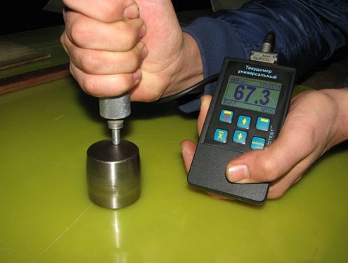
Buffalo Inspection Services uses the latest hardness testing equipment and highly trained technicians for the delivery of non-destructive testing (NDT) services, to assure that your hardness test readings are both accurate and reliable.
Hardness is the property of a material that enables it to resist “plastic deformation”, usually by penetration. However, the term hardness may also refer to the resistance to bending, scratching, abrasion or even cutting.
Hardness is not an intrinsic material property dictated by precise definitions in terms of fundamental units of mass, length and time. A hardness property value is the result of a defined measurement procedure.
Hardness of materials has probably long been assessed by resistance to scratching or cutting. An example would be material B scratches material C, but not material A. Alternatively, material A scratches material B slightly and scratches material C heavily. Relative hardness of minerals can be assessed by reference to the Mohs scale that ranks the ability of materials to resist scratching by another material. Similar methods of relative hardness assessment are still commonly used today. An example is the file test where a file tempered to a desired hardness is rubbed on the test material surface. If the file slides without biting or marking the surface, the test material would be simply considered harder than the file. If the file bites or marks the surface, the test material would be considered softer than the file.
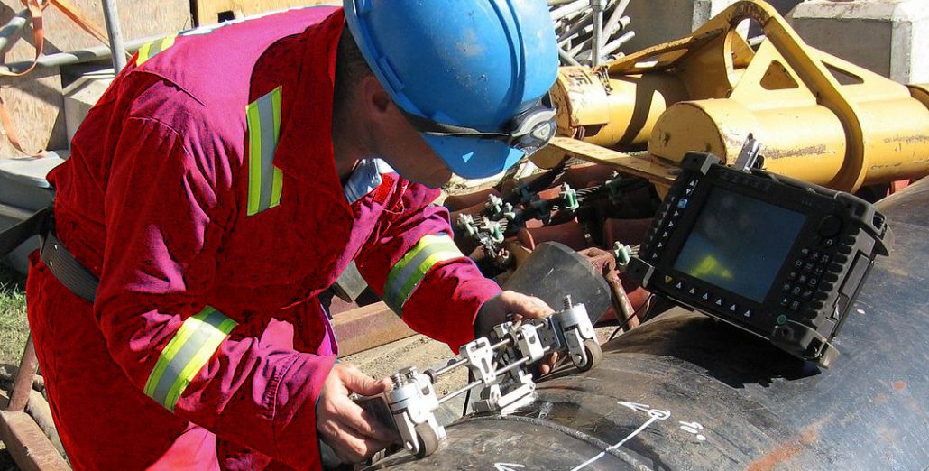
Phased array ultrasonic testing (UT) systems offer the greatest possibility of performing inspections with the ultrasonic beams of various angles and focal lengths using a single array of transducers. Software control over the beam angles and focusing is achieved by application of precisely controlled delays to both the emission pulse and received signal for each element in an array of transducers, hence the term, “phased array”.
The benefits of phased array technology over conventional UT come from its ability to use multiple elements to steer, focus and scan beams from a single piece of equipment. This gives us the ability to inspect components with complex angles/geometry with greater ease and less time.
In addition, testing welds from multiple angles provides a greater Probability of Detection of anomalies and other weld flaws. The ability to focus at multiple depths also improves the ability for sizing critical defects for volumetric inspections.
Manufacturing flaws (lack of sidewall fusion, lack of root penetration, lack of root fusion, porosity, etc.), in services flaws (fatigue cracking, stress corrosion cracking, corrosion, erosion, etc.) and parent metal flaws (inclusions and laminations) are among the defects that phased array can readily detect.
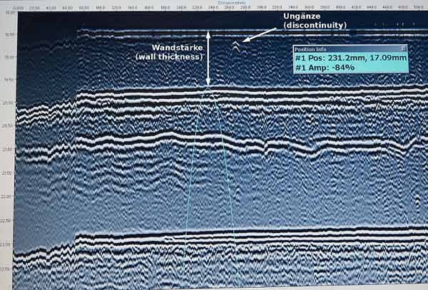
Most ultrasonic techniques rely on receiving specular reflections from defects, even if only from particular facets. Time of flight diffraction (TOFD) detects flaws using the signals diffracted from the flaw’s extremities. Two angled compression wave probes are used in transmit-receive mode, one on each side of the weld. The beam divergence is such that the majority of the thickness is inspected, although, for thicker components, more than one probe separation may be required. When the sound strikes the tip of the crack, this acts as a secondary emitter which scatters sound out in all directions, some in the direction of the receiving probe. A lateral wave traveling at the same velocity as the compression waves, travels directly from the transmitter to the receiver. The time difference between the lateral wave and the diffracted signal from the flaw provides a measure of its distance from the scanned surface. If the flaw is large enough in the through-wall dimension, it may be possible to resolve the tip-diffracted signals from its top and bottom, thereby allowing the through-wall height of the flaw to be measured.
The TOFD technique is well suited for the detection and the sizing of all types of embedded flaws, especially those planar in nature. However, the detection of small near-the-scan-surface flaws can be more difficult due to the presence of the lateral wave response which often occupies several millimeters of the depth axis on images.
To sort through this technical explanation and to determine the applicability of TOFD Ultrasonic Testing (UT) for your particular non-destructive testing (NDT) needs, please call one of our highly-qualified ultrasonics technicians. They can readily explain the limitations and the advantages of using TOFD UT.
LIBS (laser induced breakdown spectroscopy). LIBS is an optical technique.
How it works:
The Z-300 LIBS unit fires a pulsed laser at the material, creating a plasma. The on-board spectrometer measures the optical spectrum and via a factory or user-generated calibration, the on-board processor displays the elemental chemistry for all calibrated elements.
What’s unique about the Z-300 is it’s the only handheld in the world capable of providing in-field analysis of low atomic number elements like Li, Be, C, F, B, and others. The only other methods for in-field measurements of low atomic number elements like Carbon and others is through bulky spark testing equipment or via laboratory wet chemistry methods like ICP (Inductively Coupled Plasma).
Now, you can measure Carbon in seconds, simply, accurately and portably.

Magnetic Particle Inspection (MPI) is an extension of visual inspection. This critical technique for non-destructive testing (NDT) is used for the detection of surface and near-surface flaws (discontinuities) in ferromagnetic materials.
A magnetic field is applied to the test piece, either locally or overall, using a permanent magnet, electromagnet, flexible cables or hand-held prods. If the material is sound, most of the magnetic flux is concentrated below the material’s surface. However, if a flaw is present, such that it interacts with the magnetic field (disturbs it), the flux is distorted locally and “leaks” from the surface of the specimen in the region of the flaw.
We can detect this leak by applying fine magnetic particles to the surface of the specimen. These particles are attracted to the area of the “flux leakage” creating a visible indication that there is a flaw. The materials commonly used for this purpose are black iron particles and red or yellow iron oxides. In some cases, the iron particles are coated with a fluorescent material enabling them to be easily viewed under an ultraviolet lamp (black light) in darkened conditions.
Our portable power packs, yokes and equipment provide the foundation for Buffalo Inspection Services to provide fast and reliable magnetic particle examinations with a multitude of approved techniques. These include visible and fluorescent in both wet & dry formats and can be performed just as easily in a fabrication shop or out in the field.
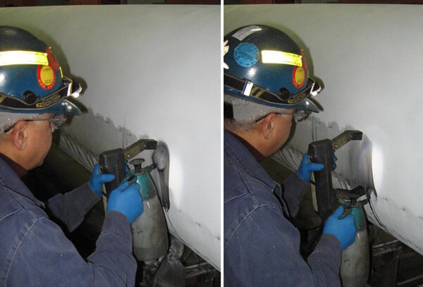
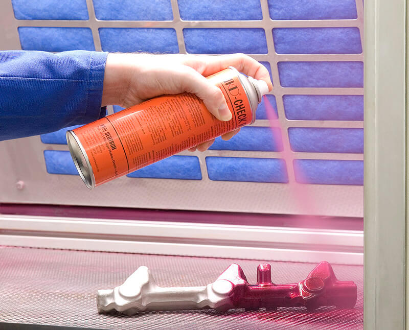
A number of different liquid penetrant inspection systems are used in the non-destructive testing (NDT )industry today. Fluorescent penetrants are normally used when the maximum flaw sensitivity is needed. However, these penetrants must be viewed under darkened conditions using an ultraviolet light source (black light). This may not always be practical, so the more commonly used LPI systems used are solvent removable or water washable red dye systems (Visible Contrast). These systems typically are comprised of three components, being 1) a cleaning fluid, 2) the dye penetrant, and 3) the developer. These systems, regardless of type, are often used to check weld quality during fabrication.
Despite being one of the most popular NDT methods, liquid penetrant testing (examination) is often incorrectly conducted. Test surfaces are not cleaned adequately, the contact time (dwell times) between the penetrant and the test surfaces are too short, or the excess penetrant is removed carelessly (i.e. from the flaws and discontinuities as well as from the test surface). For these reasons, Buffalo Inspection Services ensures that our technicians whom carry out liquid penetrant inspections are trained and certified to CGSB and ASNT/SNT-TC-1A.
As the need became more and more prominent for visual inspection, Buffalo Inspection Services rose to the challenge and formed our own Visual Inspection Department.
Visual inspection is one of the most important inspection methods. All successful NDT and Quality Systems start with a good visual inspection program. This inspection starts before welding even takes place to ensure the proper material (such as steel, tools and equipment) fit the requirements of the job. Visual inspection continues through the entire job by ensuring the welders are using the proper welding procedure(s), that rod ovens are at the proper temperatures, and the quality of the weld in process.
Visual inspection is also used for verifying the quality of the finished product. This can include such factors as dimensional checks, proper heat numbers, and a visual assessment of the quality of the weld itself. Visual inspection can enhance the efficiency as well as the quality of all jobs and is an essential part of the building and fabrication process.
Advantages of Visual Inspection
Limitations of Visual Inspection
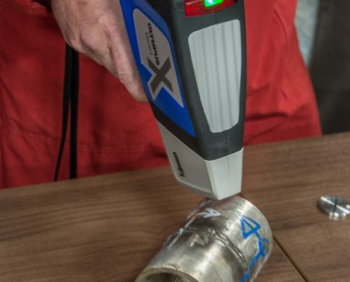
Positive Material Identification (PMI) enables a component’s material grade or chemical composition to be determined. PMI is one of the more specialized non-destructive testing (NDT) methods of which Buffalo Inspection Services readily undertakes. With the usage of positive material identification the alloy composition of materials can easily be determined. If a material certificate is missing or it is just not clear what the composition of a material is, the use of positive material identification offers the solution.
PMI is particularly used for high quality metals like stainless steel and high-alloy metals. While engineers push the boundaries of material capacities to their outer limitations in their designs, assurance that the proper material is being used becomes ever the more critical.
To provide you that assurance, Buffalo Inspection Services employs the latest high-tech equipment matched up with highly competent and trained technicians.
Ferrite testing, although seen by some as very basic, can often give indications that would perhaps only be found once something has gone wrong. Should ferrite levels drop below certain percentage levels, this can subsequently show that incorrect heat treatment has been applied to the product or the presence of third phases in the material which can be detrimental to the in-service life.
Buffalo Inspection Services uses methods that ensure obtained ferrite readings are correct and are truly relative to the samples under test. We can also test certain austenitic weld metals for “deposited” ferrite content.
At Buffalo Inspection Services, we use only the latest ferrite testing equipment available coupled with highly trained specialists conducting the tests. This will assure you that you are obtaining the most accurate information possible for your non-destructive testing (NDT) needs
Buffalo Inspection Services has been serving the NDE and NDT inspection industry since 1979. Our success has been based on responding to our client's needs - delivering safe & reliable results with uncompromised quality & transparency. We understand the need to be partners with our clients and we honour this commitment, through business intelligence to support client expansion, maintenance and asset integrity efforts.
Find a Buffalo Inspection crew near you.
Click to view full crew map & contact information.
3867 Roper Road
Edmonton, Alberta, T6B 3S5
24/7 Dispatch 780.446.8536
Toll-free: 1.800.634.8588
Phone: 780.486.7344
Fax: 780.486.4685
Unit #22, 10322 – 74th Avenue,
Clairmont, AB
T8X 5A7
Cell: 250.793.8137
Camrose, Alberta
Toll-free: 1.800.634.8588
24/7 Dispatch 780.446.8536
8712 – 107 Street, Bay #3
Fort St. John, BC
Office: 250.793.8137
Cell: 250.808.9375
Cell: 780.446.8536
Cell 1: 306.491.7446
Cell 2: 306.229.3303
24/7 Dispatch: 780.706.5881
5424 Cottonwood Road
P.O. Box 1994
VOC 1R0
Cell: 250.321.2900


Contact Buffalo to discuss NDT Inspections for your company.
Head Office: 3867 Roper Road Edmonton, AB T6B 3S5
Toll Free: 1.800.634.8588
Phone: 780.486.7344
Fax: 780.486.4685
